Shear Force
Shear force (قوة القص skjærkraft) is the internal force acting parallel to a cross-section** of a structural member, tending to make one part slide past the adjacent part.
In a beam, it is usually denoted by (V) and is measured in newtons (N) or kilonewtons (kN).
For a section of a beam:
\[V = \sum \text{vertical forces on one side of the section}\]
Shear force is important because it can cause sliding failure or contribute to diagonal cracking, especially in reinforced-concrete beams.
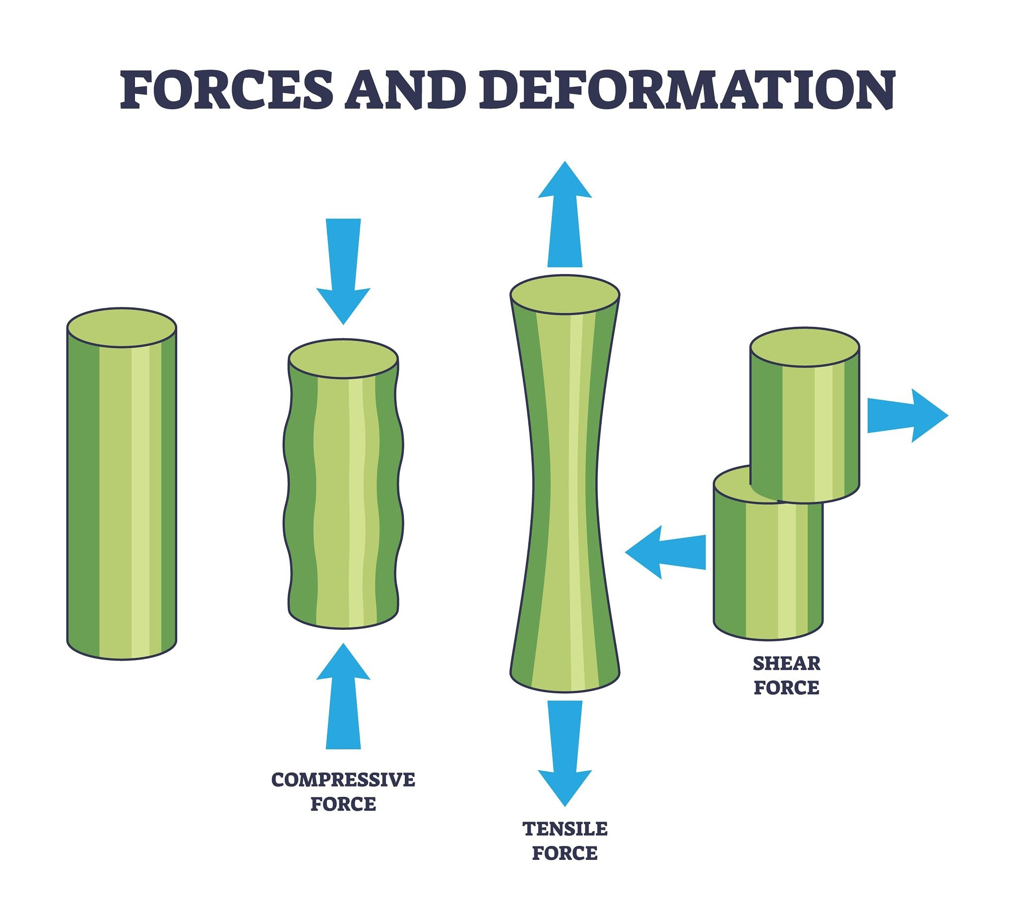
Shear forces do not elongate as tension forces or compress the material as compression forces; instead, they cause angular deformation (changing the shape of the cross-section).
Mathematically and in structural analysis, shear force (\(V\)) is the resultant of the vertical forces acting on one side of a section. It is closely related to the Bending Moment, as the shear force represents the derivative of the bending moment with respect to distance:
\[V = \frac{dM}{dx}\]
Shear Forces in Engineering Applications
How Do Shear Forces Appear in Engineering Applications?
1. In Reinforced Concrete Structures
Concrete is naturally excellent at withstanding compressive forces, but it is very weak against shear and tensile forces. When pouring concrete foundations (such as a garage floor using strong concrete like B30/B40), high shear forces are generated at the edges and support points of the slab due to the loads. For this reason, reinforcing steel (like K-131S mesh) is embedded inside the slab; the steel absorbs the shear and tensile stresses that the concrete cannot handle on its own, preventing hidden cracking and structural failure.
2. In Mechanical Design and Part Assembly
In mechanical modeling (whether designing and assembling parts in software like PTC Creo or in real-world applications), shear forces are heavily concentrated at fastening joints. For example, when maintaining a towing trailer, the pin connecting the trailer to the vehicle, or even the roller bearings, are subjected to immense shear forces. The movement of the vehicle pulls forward while the trailer's weight resists backward, creating a severe perpendicular force that attempts to "shear" the metal in half along the cross-section of the joint.
Differences Between Shear and Tensile forces
The fundamental difference lies in the direction of the force relative to the cross-sectional area of the material, which dictates the type of deformation that occurs.
Tensile force attempts to "stretch" the material, whereas shear force attempts to "tear" it or cause its internal layers to slide past one another.
| Aspect of Comparison | Tensile Force (Tension) | Shear Force (Shear) |
|---|---|---|
| Force Direction | Perpendicular to the cross-sectional area. It pulls the material outward. | Parallel to the cross-sectional area. It pushes parts of the material in opposite directions. |
| Effect on Material | Causes elongation or stretching in the direction of the force, and a reduction in the cross-section. | Causes angular deformation or sliding of the material's planes over each other. |
| Everyday Example | Stretching a rubber band, or pulling a rope in tug-of-war. | Cutting paper with scissors, or slicing meat with a knife. |
| Engineering / Mechanical Example | A steel cable in a winch pulling a heavy load, or bolts preventing two components from pulling apart. | A hitch pin in a towing trailer, or rivets joining two metal plates that are being pulled in opposite parallel directions. |
Key insight for designers: When designing mechanical components, materials are generally weaker in resisting shear forces than tensile forces. Consequently, the cross-sectional area is calculated more carefully (or larger diameter pins/bolts are used) if a joint will be subjected to shear stress.
Mathematical Analyzing
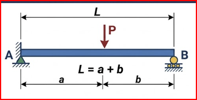
A classic fundamental example in structural engineering: a Simply Supported Beam subjected to a concentrated Point Load.
Definition of Variables
\(L\): Total length of the beam.
\(P\): Magnitude of the downward point load.
\(a\): Distance from the left support to the point of load application.
\(b\): Distance from the right support to the load (\(L = a + b\)).
- Calculating Support Reactions
Before finding the internal forces, we must calculate the external reaction forces at the supports by applying the equations of static equilibrium.
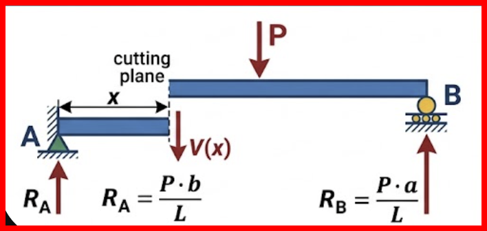
\(R_A\): Vertical reaction force at the left support.
\(R_B\): Vertical reaction force at the right support.
\(x\): Distance from the left end (start of the beam) to any cross-section being analyzed.
\(V(x)\): Internal shear force at distance \(x\).
Sum of moments about the left support (\(A\)) equals zero:
\[\Sigma M_A = 0\]
\[(R_B \cdot L) - (P \cdot a) = 0\]
\[R_B = \frac{P \cdot a}{L}\]
Sum of vertical forces equals zero:
\[\Sigma F_y = 0\]
\[R_A + R_B - P = 0\]
\[R_A = P - R_B = P - \frac{P \cdot a}{L}\]
Since \(L = a + b\), the equation for \(R_A\) can be simplified:\(R_A = \frac{P \cdot (L - a)}{L} = \frac{P \cdot b}{L}\).
Calculating Shear Force Equations \(V(x)\)The shear force is calculated mathematically by making an imaginary cut in the beam at a distance \(x\) and finding the resultant of all vertical forces to the left of the section. The beam is divided into two segments due to the concentrated load.
- Segment 1: Before the point load (\(0 \le x < a\))
When cutting the beam in this segment, the only external force acting to the left of the section is the upward reaction \(R_A\).
The internal shear force \(V\) (downward according to positive sign convention) resists this force:
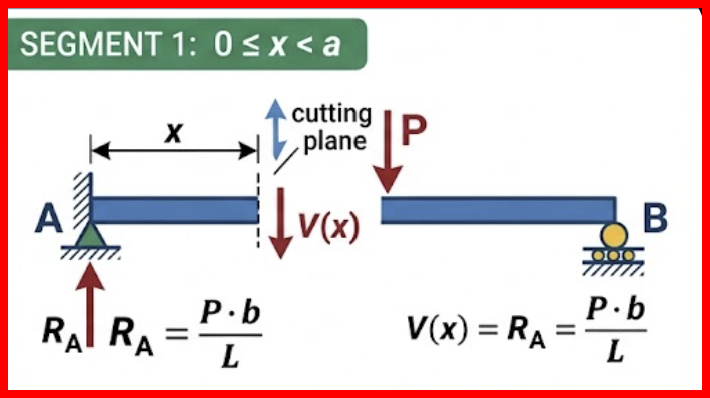
\[\Sigma F_y = 0 \implies R_A - V(x) = 0\]
\[V(x) = \frac{P \cdot b}{L}\]
(The shear force here is positive and constant along this entire segment).
- Segment 2: After the point load (\(a < x \le L\))
When analyzing a section located after the load \(P\), the downward load \(P\) enters the equilibrium equation for the left portion:
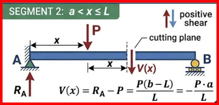
\[\Sigma F_y = 0 \implies R_A - P - V(x) = 0\]
\[V(x) = R_A - P\]
Substituting the previously calculated value of \(R_A\):\(V(x) = \frac{P \cdot b}{L} - P\)
Since \(b - L = -a\), the equation becomes:
\[V(x) = -\frac{P \cdot a}{L}\]
(The shear force here is negative and constant, and it is exactly equal to the opposite reaction \(-R_B\)).
Mathematical Interpretation
The shear force is constant within each segment, but exactly at the point \(x = a\), there is a sudden drop (a mathematical discontinuity) in the value by a magnitude of \(P\), dropping from the positive value \(\frac{P \cdot b}{L}\) to the negative value \(-\frac{P \cdot a}{L}\).
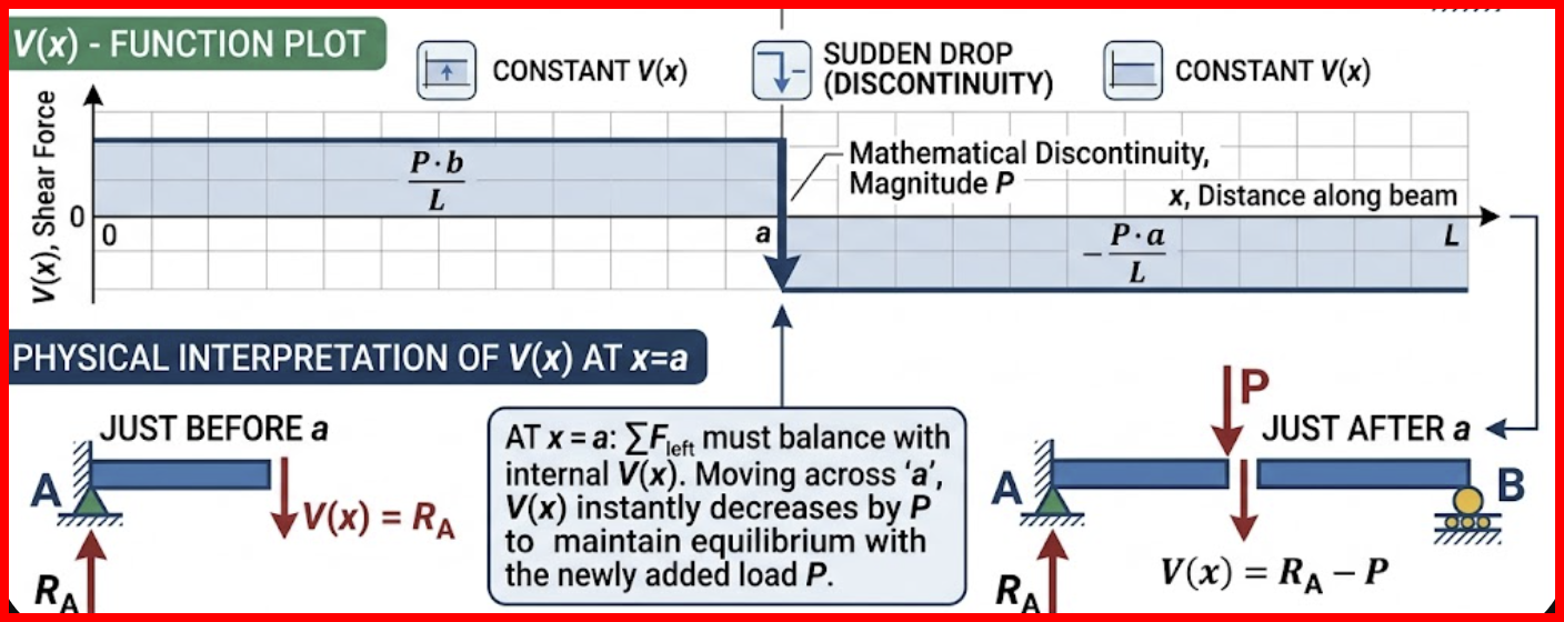
\[V(x) = \begin{cases} \frac{P \cdot b}{L}, & x < a \\ -\frac{P \cdot a}{L}, & x > a \end{cases}\]
the value of the function exactly at the point \(x = a\) is undefined, and there is a mathematical discontinuity (a jump) at this location.
In structural engineering and beam analysis, a point load \(P\) is a mathematical idealization assuming the force acts on a theoretical point with zero area. Because of this assumption, the shear force drops abruptly and vertically at point \(a\) by the magnitude of the load \(P\). Consequently, a single value cannot be determined for the function exactly at \(x = a\).
Instead, the function is evaluated using limits to determine the internal forces immediately before and after the application point:
- Limit from the left: As \(x\) approaches \(a\) from the left
(\(x \to a^-\)), the value is:
\[V(a^-) = \frac{P \cdot b}{L}\]
- Limit from the right: As \(x\) approaches \(a\) from the right
(\(x \to a^+\)), the value is:
\[V(a^+) = -\frac{P \cdot a}{L}\]
Physical Reality
In actual engineering applications, no force acts on a zero-dimensional point. The load is always distributed over a small contact area. If this real-world distribution is accounted for, the shear force diagram does not drop vertically. Instead, it transitions via a steeply sloped line connecting the positive and negative values, making the function continuous and yielding a specific value (passing through zero) at the exact center of the load's contact area.
The Relationship Between Shear and Load
Building the fundamental calculus entirely on idealized point loads, the load value would be zero almost everywhere along the beam and undefined at specific points, making continuous integration impossible.
Unlike a point load (\(P\)) which applies a concentrated force at a single specific mathematical point, a distributed load (or continuous load) is spread out over a continuous length of the structural member.
Applying the equilibrium condition for vertical forces (\(\Sigma F_y = 0\)) to the same differential element (assuming upward is positive):
\[V - w(x)dx - (V + dV) = 0\]
\[-dV - w(x)dx = 0\]
\[\frac{dV}{dx} = -w(x)\]
This proves that the derivative of the shear force yields the value of the distributed load with a negative sign.To prove this relationship mathematically, we isolate an infinitesimally small differential element of length \(dx\) from the beam and apply the conditions of static equilibrium for forces and moments to it.
In the differential derivation \(\frac{dV}{dx} = -w(x)\), the term \(w(x)\) is kept as a generalized function so the calculus holds true regardless of whether the load is perfectly flat, sloped, or highly irregular.
Shear Force and Bending Moment
By isolating an infinitesimally small differential element of length \(dx\) from the beam and apply the conditions of static equilibrium for forces and moments to it.
1. Defining the Forces and Moments Acting on Element \(dx\)
Assuming this element is subjected to a downward distributed load \(w(x)\).
- On the left face (at distance \(x\)): A shear force \(V\) (upward) and a bending moment \(M\) (clockwise) act on the element.
- On the right face (at distance \(x + dx\)): These values change by a small differential amount due to the additional distance, becoming a shear force \(V + dV\) (downward) and a bending moment \(M + dM\) (counterclockwise).
- External load: A total force resulting from the distributed load, with a magnitude of \(w(x) \cdot dx\), acts on the element and is concentrated at its center (at a distance of \(\frac{dx}{2}\) from both faces).
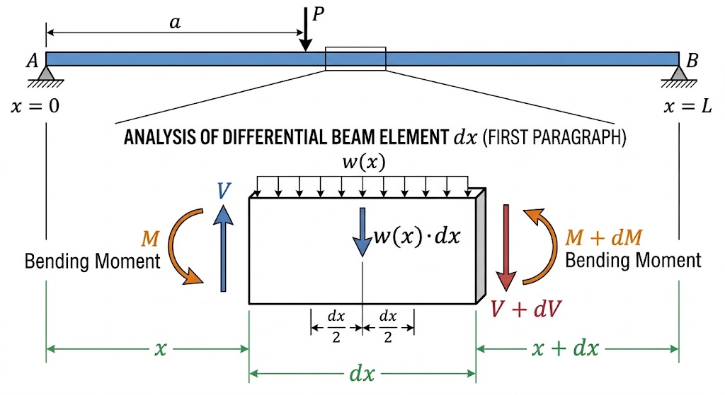
2. Moment Equilibrium to Prove the Relationship (\(\Sigma M = 0\))
Taking the sum of the moments about the right face of the element (at \(x + dx\)). Assuming clockwise rotation is the positive direction:
\[M + V \cdot dx - w(x) \cdot dx \cdot \left(\frac{dx}{2}\right) - (M + dM) = 0\]
\[V \cdot dx - dM - w(x) \frac{(dx)^2}{2} = 0\]
In calculus, the value \(dx\) is infinitesimally small. Consequently, its square \((dx)^2\) approaches zero and is considered a second-order infinitesimal (higher-order term), making it geometrically and mathematically negligible compared to the other terms. By dropping this term, the equation becomes:
\[V \cdot dx - dM = 0\]
\[dM = V \cdot dx\]
\[V = \frac{dM}{dx}\]
3. The Integral Deduction
To prove the integral relationship, we rearrange the derived differential equation \(dM = V \cdot dx\) and integrate both sides between two points \(x_1\) and \(x_2\) (which correspond to the bending moments \(M_1\) and \(M_2\)):
\[\int_{M_1}^{M_2} dM = \int_{x_1}^{x_2} V(x) dx\]
\[M_2 - M_1 = \int_{x_1}^{x_2} V(x) dx\]